
The rapid adoption of LEDs in various applications makes simple drive solutions such as linear regulators impractical in many cases. In general, simple drive schemes continuously deliver power from the input source to the driver's output while using resistive elements to program the desired LED forward current. For the same LED current, the losses in these resistive elements increase considerably as the line voltages increase. For example, a linear regulator based LED driver yields 70 percent efficiency when supplying 1 amp from a 5-volt input source to a typical white InGaN LED (VF = 3.5V). Under the same operating conditions, the driver's efficiency will drop to approximately 30 percent when the input voltage increases to 12 volts. Such poor efficiencies require impractical thermal management schemes.
Switching regulators
Switching regulators improve the conversion efficiency. They interrupt the power flow while controlling the conversion duty cycle to program the desired output voltage or output current. Interrupting the power flow results in pulsating current and voltage and therefore it necessitates the use of energy storage elements (inductors and/or capacitors) to filter these pulsating waveforms. Contrary to linear regulators, switching regulators can be configured in different arrangements to realize voltage or current step-down (buck), step-up (boost) or both (buck-boost) functions. They are also capable of achieving high conversion efficiencies across wide input/output range. Replacing the linear regulator with a buck-based LED driver in the previous example yields 95 to 98 percent efficiency across the 5-to-12 volt input range.
The configuration flexibility and the efficiency improvements of switching regulators come at the expense of higher noise generation caused by the periodic switching events, as well as higher premiums and reduced reliability due to their perceived complexity. Constant-current LEDs favor regulator topologies that can be simply configured as a constant-current source. The selected topology should also combine high performance with minimum component-count to increase the driver's reliability and to reduce cost. It should also facilitate the use of various dimming techniques to take advantage of the LEDs dynamic light- tuning characteristic. Fortunately, the most basic step-down (buck) switching topology enjoys all these characteristics, making it the regulator of choice to drive LEDs whenever possible.
Constant-current power stage
Switching regulators are most commonly known as voltage regulators. Figure 1a illustrates a basic constant-voltage buck regulator. The buck controller maintains a constant output voltage as the line voltage changes by varying the operating duty cycle (D) or the switching frequency. The desired output voltage set point is programmed using the following equation (Eq. 1):

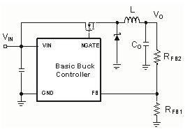
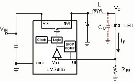
The inductor, L, is selected to set the peak-to-peak current ripple, ΔIpp, while the capacitor, Co, is selected to program a desired output-voltage ripple and to provide output-voltage hold-up under load transients. The average inductor current in a buck converter is equal to the load current, and, therefore, we can set the load current by controlling the peak-to-peak inductor-current ripple. This significantly simplifies the conversion of a constant-voltage source into a constant-current source. Figure 1b illustrates a basic constant-current buck regulator. Similarly, constant-current buck regulators provide line regulation by adjusting the conversion duty cycle or the switching frequency, and the LED current, IF, is programmed using the following equation (Eq. 2):

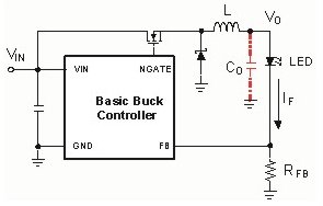
After we set the LED current, IF, we must properly sense the inductor current. Theoretically, multiple current sense schemes such as MOSFET Rdson sensing and inductor DCR sensing can be used. However, practically, the current sense precision of some of these would not meet the required LED current set point accuracy (5 to 15 percent for a high brightness LED (HB-LED). If we directly sense IF through an inline resistor, RFB, we can secure the needed precision, but there may be excessive power dissipation in the current-sense resistor. Lowering the feedback voltage, VFB, allows the use of lower resistance values for the same IF (Eq. 2), which minimizes losses. The newer dedicated LED drivers generally offer reference voltages (feedback voltages) within the range of 50 to 200 millivolts.
Uniquely, constant-current buck-driven regulators can be configured without output capacitance. The use of the output capacitor, Co, in these regulators is limited to AC current filtering since they inherently do not experience load transients and have continuous output currents. When we configure a constant-current buck regulator without output capacitance, we substantially increase the converter's output impedance and, in turn, boost the converter's ability to rapidly change its output voltage so that it can maintain a constant current. As a result, the dimming speed and dimming range of the converter improve significantly. Wide dimming range is valuable feature in applications such as backlighting and machine vision.
On the other hand, lacking the required output capacitance, AC-current-ripple filtering circuitry necessitates the use of higher inductance values in order to meet the LED manufacturers recommended ripple current (ΔIF = ±5 to 20 percent of the DC forward current). At the same current rating, higher inductance values increase the size and cost of the LED driver. Consequently, the use of output capacitors in constant-current buck-based LED drivers is governed by a tradeoff between cost and size versus dimming speed and dimming range.
For example, in order to drive a single white LED (VF ≈ 3.5 volts) at 1 amp with a ripple current, ΔIF, of ±5 percent from an input of 12 volts at 500 kHz requires a 50 microhenry inductor with a current rating of 1.1 amps. However if the inductor ripple-current is allowed to increase to ±30 percent, then the inductance required is less than 10 microhenries. For the same core material and at approximately the same current rating, a 10 microhenry inductor will be typically offered at roughly half the size and cost of a 50 microhenry inductor. To attain the desired ΔIF (±5 percent) using the 10 microhenry inductor, the output capacitance required is calculated based on the dynamic resistance, rD, of the LED, the sense resistance, RFB, and the impedance of the capacitor at the switching frequency, using the following expression (Eq. 3):


Control-loop schemes
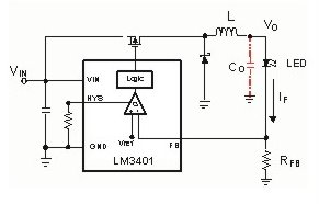
Buck-based power stages are well-matched to several control-loop schemes and free of stability limitations such as right-half-plane zeros. They uniquely facilitate the shunt PWM dimming approach in addition to being compatible with other dimming methods. This provides the system designer with configuration flexibility when designing an LED driver for specific requirements. Hysteretic control is well-suited for applications such as light bulbs and traffic lights, in which variable switching frequencies are tolerated or where narrow input-voltage range supplies are used. Hysteretic control doest not experience control-loop bandwidth restrictions, which eliminates the need for loop compensation because of its inherent stability. Utilizing hysteretic control to drive a buck-based LED driver (Fig. 2a) greatly simplifies the design as well as reduces the component count, and the cost of the driver. This configuration also yields superior PWM dimming ranges that outperform other buck-based schemes. Using hysteretic buck-based LED drivers with the shunt-dimming approach is well-suited for applications that require ultra-wide dimming ranges at high dimming frequencies and that can tolerate variable switching frequencies.
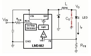
Quasi-hysteretic buck-based LED drivers offer a good compromise between fixed-frequency operation and hysteretic control for applications in which variable switching frequencies may not be desired. The controlled on-time (quasi-hysteretic) buck-based LED driver (Fig. 2b) employs a control scheme based on a hysteretic comparator and a one-shot on-timer which is used to set a controlled on-time. This controlled on-time is programmed so that it is inversely proportional to the input voltage, and, therefore, it minimizes the switching frequency variations as the line voltage changes. Using this scheme also eliminates the need for control-loop bandwidth limitations, enabling it to achieve wide dimming ranges when used with different dimming configurations.
In some cases, as in a number of automotive applications, synchronizing the LED driver(s) to an external clock or to each other may be required to minimize noise interference. Implementing the frequency synchronization feature with the non-clock-based hysteretic and quasi-hysteretic scheme can be challenging. In contrast, this feature can be simply realized in clock-based regulators such as the fixed-frequency buck LED driver shown in Fig. 2c. Fixed frequency control generally yields a more complex solution, and it limits the dimming range of the driver regardless of the dimming approach due to its dynamic response limitations.
In summary, there are many characteristics that make buck-based regulators attractive LED drivers. They are simple to configure as a current source and can be realized with minimum component counts, which simplifies the design process, improves the drivers' reliability, and reduces cost. Buck-based LED drivers also provide configuration flexibility since they are compatible with multiple control schemes. They also allow for high-speed dimming as well as wide dimming ranges since they can be configured without output capacitance and are well-matched to various dimming approaches including shunt dimming. All these features make buck-based (step-down) LED drivers the topology of choice whenever the application permits.
What if the application does not permit their use? Applications such as residential and commercial lighting require thousands of lumens, creating a need to drive LED strings. The total forward voltage drop of an LED string is equal to the sum of the forward voltage drops of all the LEDs in the string. In some cases, the input voltage range of the system can be lower than the forward voltage drop of the LED string, or it can vary so that sometimes it's lower and sometimes it's higher. These scenarios would require either boost, or buck-boost switching regulators. In the next installment, we discuss the challenges of using boost and buck-boost topologies to drive LEDs.
About the authors
Sameh Sarhan is a staff applications engineer for the Medium Voltage/High Voltage Power Management group in Santa Clara, CA. He has been involved with power electronics in various forms since 1998, having worked for FRC Corp. and Vicor Corp. His experience includes the design of hard/soft switching power supplies from a few watts to 600 watts. Sameh received a bachelor's degree in electronics engineering in 1996 from Cairo University (Egypt).
Chris Richardson is an applications engineer in the Power Management Products group, Medium and High Voltage Division. His responsibilities are divided between lab work, bench evaluation of new ICs, written work such as datasheets and applications notes, and training for field engineers and seminars. Since joining National Semiconductor in 2001, Chris has worked mainly on synchronous buck controllers and regulators. In the last three years he has focused on products for the emerging high brightness LED market in the automotive and industrial areas. Chris holds a BSEE from the Virginia Polytechnic Institute and State University.