
以前的设计方案阐明了一个通常困扰模拟设计者的处理方法:讨厌的接地回路(参考文献1)。那个设计方案描述了一个简单而有效的多通道电路。但它是不对称的CMV(共模电压)方法,只适用于总线接收端。因此,它只应用于信号输入,而对输出无效。然而,CMV如果由纯交流噪声组成,一个不同的CMV修正方案——有源传导消除——双向工作,且因此抵消输入和输出信号上的CMV误差成分。
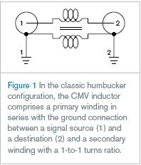
工程师常年使用无源CMV感应消除(图1)。有时被称作“humbucker变压器”,因为能量干线的60Hz“嗡嗡声”通常为CMV成分,CMV感应由信号源(1)和目标(2)之间的初级线圈与地连接组成,次级线圈有1到1的转换率。
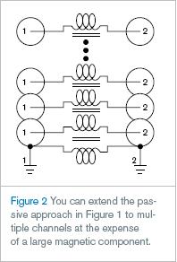
CMV变压器依靠初级和次级之间的磁耦合原理,例如任何初级线圈中电压在次级线圈中都会感应出同向和反向电压,从而消除电压。可以简单的通过增加更多次级线圈扩展原理到多信号通道——每个通道都有一个次级线圈(图2)。
然而实际上,CMV变压器的Achilles heel将分贝降到噪声频谱的低频端。线圈的感应电抗必须远大于电缆阻抗,噪
声抵消导致这个情形出现。数百毫亨的电磁感应对满足低到60Hz频率标准是必要的。对多通道应用,需要消除低到60Hz频率,转换到许多铜、核心、体积和重量。然而,如果对设计消耗的功率不介意,可以使用接地:有源驱动CMV核。
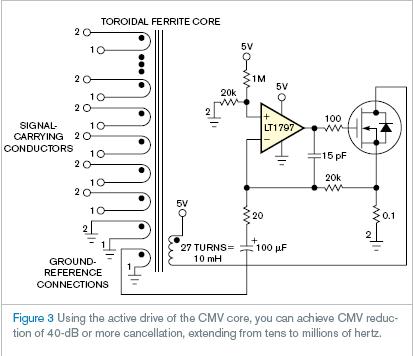
图3中,由LT1797高频运放和MOSFET组成的功率放大器驱动核,精确的抵消对参考地连接敏感的CMV。结果这些显著的线圈感应大大增加,可以减少“线圈”到简单的单一环形核通带。也就是说,一旦通过“圆环上的孔”,需要多触电信号线完成CMV40dB或更抵消,从十几到数百万Hz的范围内。
英文原文:
Actively driven ferrite core inductively cancels common-mode voltage
Active inductive noise cancellation cancels common-mode-voltage error components in both inut and output signals.
W Stephen Woodward, Chapel Hill, NC; Edited by Charles H Small and Fran Granville -- EDN, 12/14/2007
An earlier Design Idea illustrated one approach to that traditional headache for the analog designer: the dreaded ground loop (Reference 1). That Design Idea described a simple and efficient multichannel circuit. But it’s an asymmetrical CMV (common-mode-voltage) approach in that it works only at the receiving end of a cable. It therefore applies only to signal inputs and does nothing for outputs. However, in cases in which CMV consists of purely ac noise, a different CMV-remediation method—active inductive cancellation—works bidirectionally and therefore cancels CMV-error components in both input and output signals.
Engineers have for many years used passive-CMV inductive cancellation (Figure 1). Sometimes called a “humbucker transformer” because the power mains’ 60-Hz “hum” is often a dominant CMV component, the CMV inductor comprises a primary winding in series with the ground connection between the signal source (1) and the destination (2) and a secondary winding with a 1-to-1 turns ratio.
The principle of the CMV transformer relies on magnetic coupling between the primary and the secondary, such that any voltage that appears across the primary induces an equal and opposite voltage in the secondary, thus canceling it. You can easily extend the principle to multiple signal channels simply by adding more secondary windings—one secondary for each channel (Figure 2).
However, the Achilles’ heel of the CMV t
ransformer is the fact that the decibels of cancellation fall off at the low-frequency end of the noise spectrum. This situation occurs because noise cancellation depends on the fact that the inductive reactance of the windings must be much larger than the impedance of the cable. Hundreds of millihenries of inductance are necessary to satisfy this criterion for frequencies as low as 60 Hz. For multichannel applications requiring cancellation for frequencies as low as 60 Hz, this fact translates to lots of copper, core, bulk, and weight. However, if you don’t mind if your designs consume a little power, then a work-around exists: actively driving the CMV core.
In Figure 3, the power amplifier comprising the LT1797 high-frequency op amp and MOSFET forces the driven core to precisely cancel CMV as sensed in the ground-reference connection. The result is such a large multiplication of the apparent winding inductance that you can reduce the “windings” to a simple single pass-through of the toroid core. In other words, you need to thread a multiconductor-signal cable only once through the “hole in the doughnut” to achieve CMV of 40-dB or more cancellation, extending from tens to millions of hertz.