
设计者通常使用0-20mA和0-10v隔离输入作为工业应用控制的信号。利用独立电源的组合,隔离的电源、嵌入的隔离Analog Devices公司的AD7400 Σ-Δ调节器,和Texas Instruments公司MSP430微处理器结合创造一个工业设计师需求的完整的、隔离的、稳定的模拟信号接口的设计方案。一个高精度信号调理电路产生AD7400需求的微弱差分电压(图1)。电路产生所需的200mV差分电压。为明确起见,图中省略了过压二极管和保护电路。

通过适当规模的电阻R2,0-20mA电流回路转化为电压,然后进入精密运算放大器。信号连接到负输入端,通过在放大器正输入端维持一个恒定电压,获得正向偏置。而0-10v的信号,例如来自一个电位器,规模与0-20mA电流信号时的电压规模相似,并且合计到Analog Devices公司OP1177放大器IC1的负端口。
平移信号到0V以上,导致信号类似于一个正单向模拟信号。差分ADC驱动放大器Analog Decives公司的AD8138驱动AD7400。这样的合成信号增益等级为ADC需求的±200mV。最后,在连接到AD7
400之前,信号通过一个低通滤波器,其中R10、R11和 C4放于正向和负向端口之间。AD7400转换差分信号,使用低成本微处理器处理。Σ-ΔADC调解器,例如AD7400,常用连接到FPGA或DSP。不过,这种做法在成本和复杂性上要付出很高代价。对成本敏感的应用不需要进一步的滤波器,可以使用简单的微处理器。
AD7400有两个输出,MCLKOUT和MDAT(图2)。MCLKOUT,一个10MHz的时钟,与被调制的数据流MDAT同步。AD7400定义MDAT为占一段时间的百分比。由于MDAT只在MCLKOUT的上升沿发生变化,电路必须一起同步MCLKOUT和MDAT信号,产生微处理器可以计数的脉冲信号流。微处理器首先反转MCLKOUT,来防止MDAT转换边缘处产生毛刺而被计数。图中显示了MDAT,反转MCLKOUT以及由此产生的数据流。

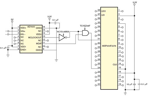
脉冲调制的数据信号和反转的MCLKOUT信号都分别连接到位于微处理器上的定时器/计数器(图3)。 TI的MSP430F2274提供了两个16位计数器,并能够支持最高16MHz的运行速度。当时钟计数器发出一个溢出中断信号时,通过采样数据计数器,电路测量ADC的转换值。这样,在循环缓冲中运行平均数量的测量数据可方便地对数据滤波。
英文原文:
Build a complete industrial-ADC interface using a microcontroller and a sigma-delta modulator
Handling both 0 to 10V and 0- to 20-mA inputs, this circuit digitizes the inputs and feeds a low-cost microcontroller.
Patrick Weber and Craig Windish, Siemens Energy and Automation, Pittsburgh, PA; Edited by Charles H Small and Fran Granville -- EDN, 7/5/2007
Designers commonly use 0- to 20-mA, 0 to 10V isolated inputs for industrial-application-control signals. A combination of isolated supplies, the built-in isolation of an Analog Devices AD7400 sigma-delta modulator, and a Texas Instruments MSP430 microcontroller creates a design for industrial designers requiring complete, isolated, and robust analog-signal interfaces. A precise signal-conditioning circuit generates the small differential voltage that the AD7400 requires (Figure 1). The circuit generates the required 200-mV differential voltage. For clarity, the figure omits overvoltage diodes and protection circuits.
A 0- to 20-mA current loop converts to a voltage through a properly scaled resistor, R2, and enters a precision operational amplifier. The signal level, which connects to the negative input, gets a positive offset by maintaining constant voltage on the positive input of the amplifier. The 0 to 10V signal, such as that from a potentiometer, also scales to a similar voltage to that of the 0- to 20-mA signal and gets summed into the negative termi
nal of the Analog Devices OP1177 amplifier, IC1.
Shifting the signal above 0V results in a signal that is similar to a positive, single-ended analog signal. A differential ADC-driver amplifier, Analog Devices’ AD8138, drives the AD7400. The gain scales such that the resultant signal is within ±200 mV, which the ADC requires. Finally, before connecting to the AD7400, the signal runs through a lowpass filter, which R10, R11, and C4 create between the positive and the negative terminals. The AD7400 converts this differential signal and processes it using a low-cost microcontroller. Sigma-delta-modulator ADCs, such as the AD7400, commonly interface to an FPGA or a DSP. However, this approach comes at a high price in both cost and complexity. For cost-sensitive applications not requiring advanced filtering, you can use a simple microcontroller.
The AD7400 device has two outputs, MCLKOUT and MDAT (Figure 2). MCLKOUT, a 10-MHz clock, synchronizes the modulated data stream, MDAT. The AD7400 interprets MDAT as a percentage of ones over time. Because MDAT changes only at the rising edge of MCLKOUT, the circuit must AND together MDAT and MCLKOUT to create a stream of pulses that the microcontroller can count. The microcontroller first inverts MCLKOUT to prevent unintentional glitches from being counted at the transition edges of MDAT. The figure shows MDAT, inverted MCLKOUT, and the resulting data stream.
The pulsed data signal and the inverted MCLKOUT each feed into a separate timer/counter on the microcontroller (Figure 3). The TI MSP430F2274 provides two 16-bit counters and can support operation as fast as 16 MHz. The circuit measures the ADC value by sampling the data counter when the clock counter signals an overflow interrupt. For this application, running an average number of data measurements on a circular buffer may conveniently filter the data.